Project 3 - Building a Camera from an Argus 3 Core
The Argus 3 camera used a Raytheon BST core with supporting control PCB and LCD display. The control PCB added on-screen graphics, image capture, zoom and safeguard controls for fire use, along with some
standardisation of core settings. The LCD was a stand-alone video in colour display, although good for its' time is poor by modern standards compromised by using NTSC composite video input.
The Argus 3 used the digital data from the Raytheon SECCA PCB, not the analogue output. However the analogue, and means to power it was provided to allow the core sub-assembly to be classed as a 'camera' for customs purposes.
These connections, and the fact that the BST core itself was designed for use in a simpler 'volts in - video out' stand alone camera such as the Raytheon Palm IR and vehicle vision products, makes it very suitable for repurposing.
A functional core using the Argus 3 detector PCB can readily be reverse engineered to provide a 'volts in - video out' stand alone camera, in a smaller volume than the full Argus3 chassis and giving access to more controls via software and
access to digital video data. The output in this case will the basic corrected core video and without the added graphics of the Argus3 camera.
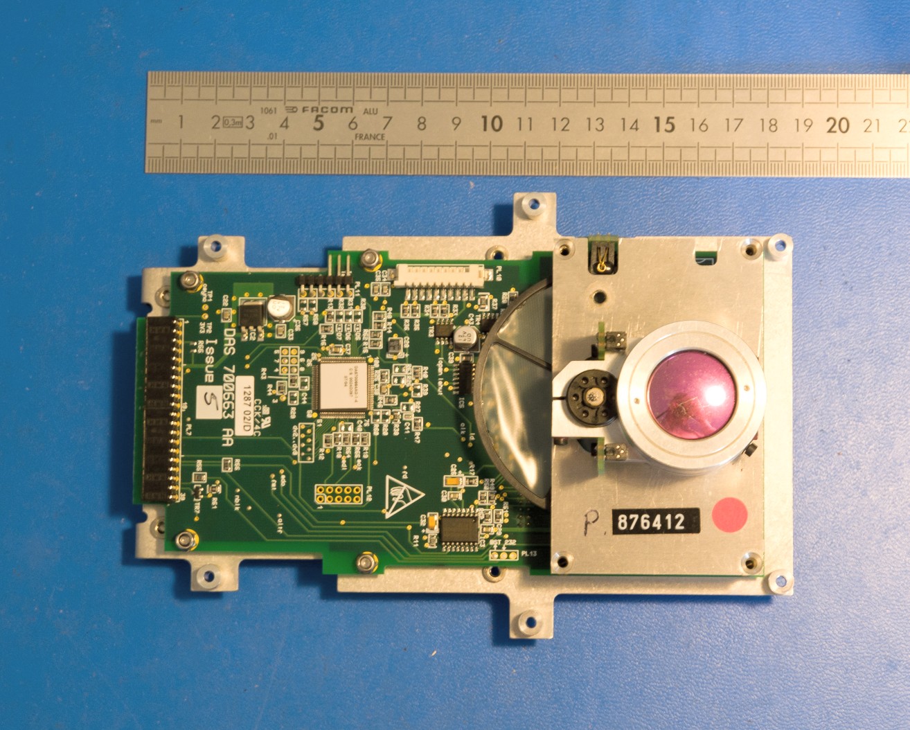
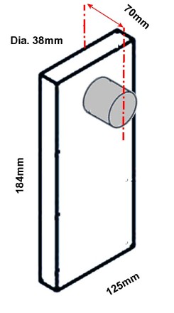
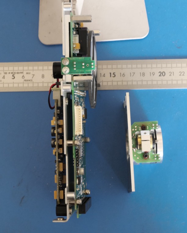
The core fits inside a 'brick' of frontal area 125x184 mm, 70mm deep including the standard lens. The chopper diameter is 70mm and is fully enclosed within the frontal area.
PCB Tour & Block Diagram
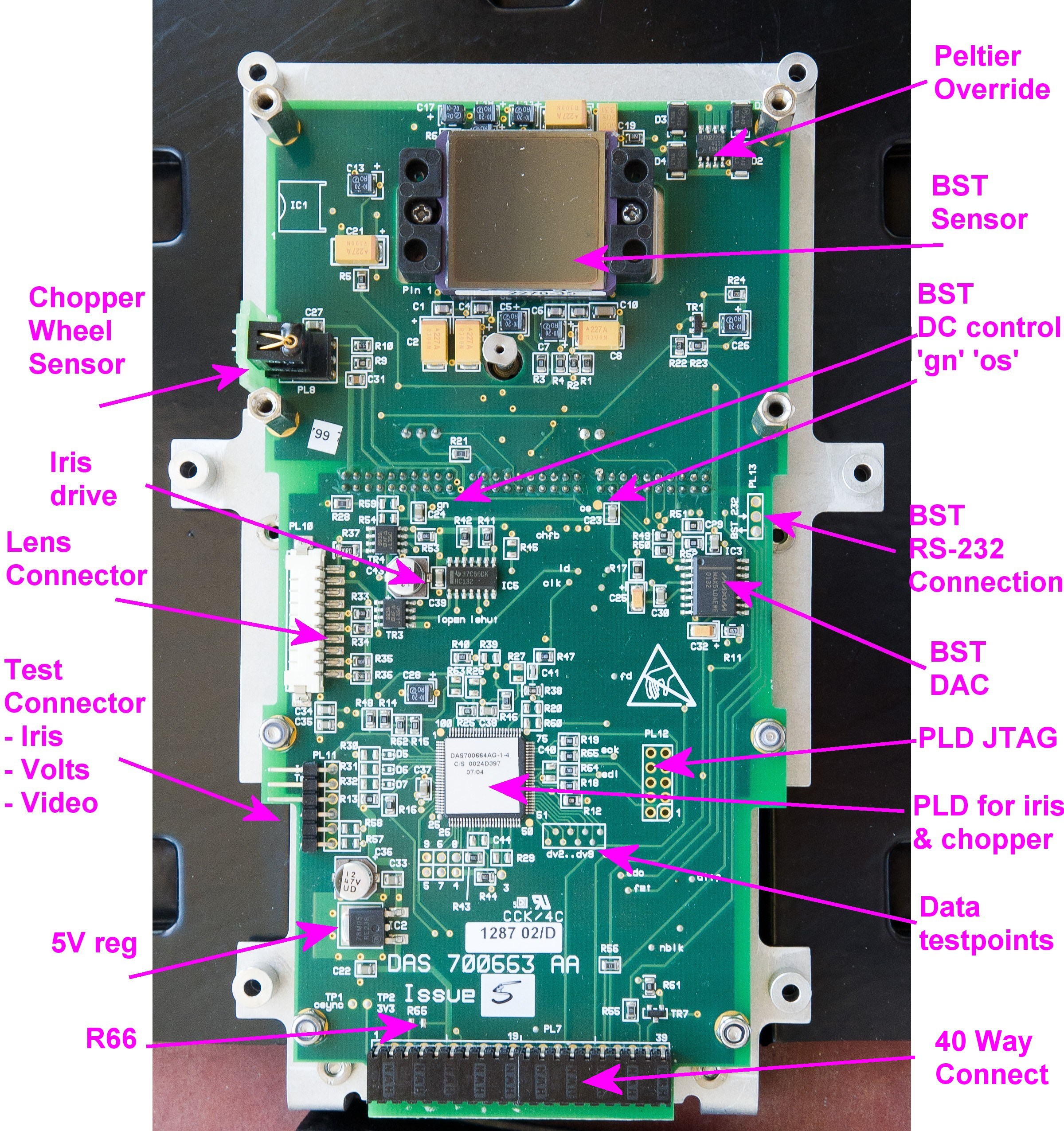
The Detector PCB has all the necessary circuitry to run the Raytheon core as a stand alone 4 wire 'volts in - video out' unit, while the 40 way bottom header connection has all necessary functions available..
PCB functions, clockwise from the top
Peltier override, allowed the EEV circuits to interrupt the peltier if the camera got too hot, also to assist startup.
BST sensor
Test points on DC control voltages for the BST core gain & Offset
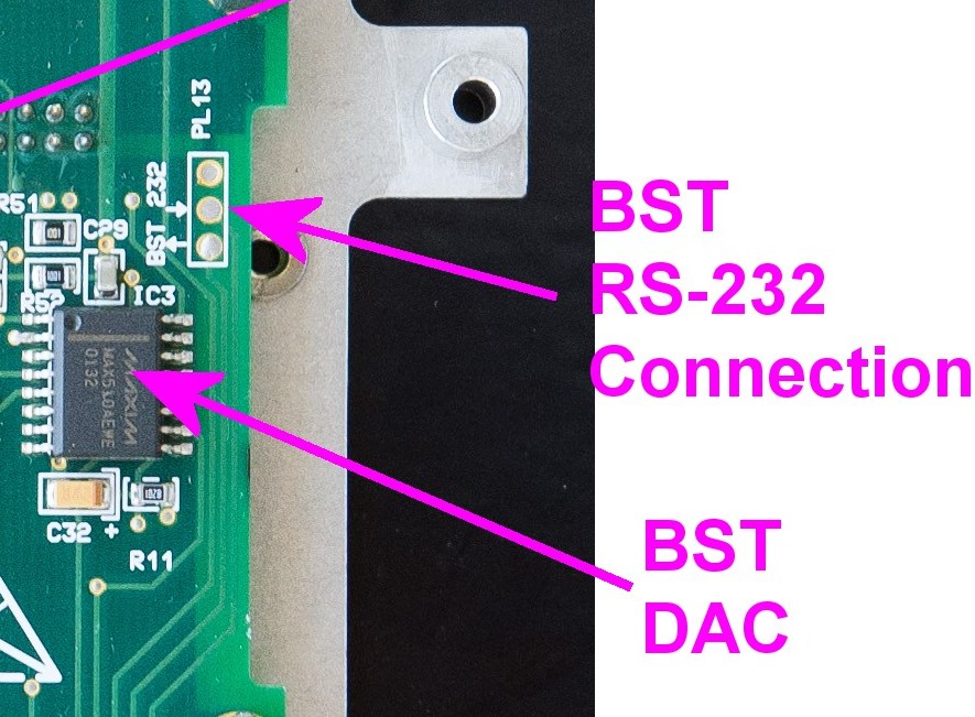
RS-232 connection for direct control of BST core image processing
The 'BST DAC' sets up analogue voltages to control the core video gain and offset. Control by SPI from EEV boards via 40 way connector
JTAG header for PLD
The detector PCB PLD controls the iris in the lens by sampling the digital video stream and also shift logic to rephase the chopper wheel to match the mechanical arrangement of the Argus3. It has the digital data available (for iris control) so could be repurposed
Testpoints on the 8 bit video data bus (upper bits of 10 from the core)
40 way connector, 0.1" pitch with all necessary signals present, so can be a single connection
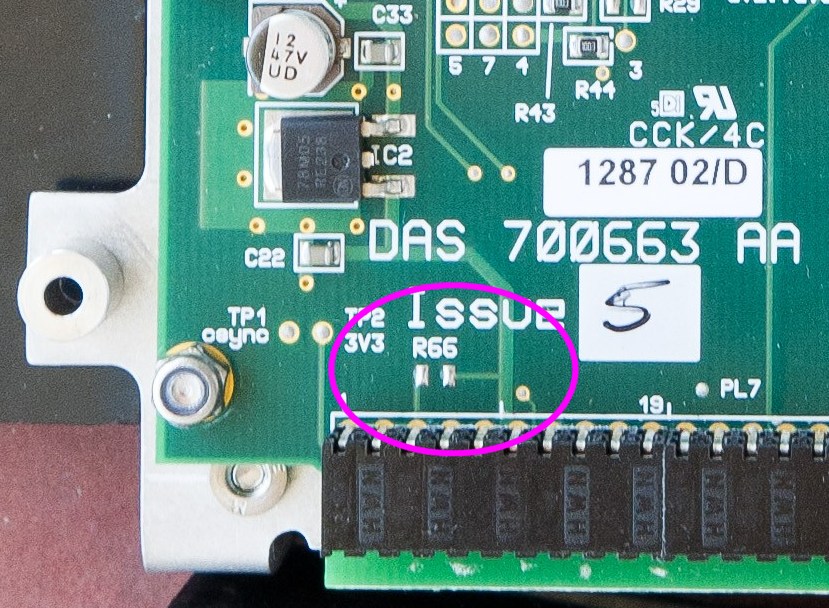
R66, a link to allow the 5V regulator to receive input power
5V regulator
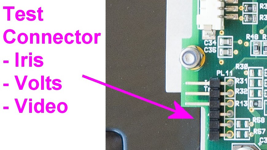
6 way 0.1" test connector with iris test, power in and video out.
Lens connector, used for iris drive and limiting
Iris drive, H bridge style pulsed power for the iris motor
Chopper wheel sensor, detects the edge notch in the chopper wheel to allow it oto be synced to the video timing. As it is not the same angle as in the Raytheon basic design, the PLD has to phase shift the pulse
It should also be noted that a large number of test points exist, all labelled with the signal names, hopefully fairly obvious.
Use as 4-wire stand alone camera core
Power Input / Video output
An explicit power and video connection is present on the detector PCB as a 6 pin 0.1" header PL11. On a 'used' PCB from a camera the bottom 3 pins are cut off to avoid case shorting so will need replacing to suit the end recasing.
Additionally the 5V regulator on the detector board needs to be powered, as it would normally use the 10V supply used for the LCD. Fit a 0R0 or wire link at R66 to join the '10V' input to the main input power. This arrangement will require a minimum input voltage of 7.5V
WARNING
The boards DO NOT include reverse polarity or spike protection. Protection should be considered if the core is not powered from a clean DC supply. A number of 'DIY' conversions to vehicle use have failed as car alternator spikes will kill the BST core, mainly through poorly specified tantalum capacitors.
At startup there is a power surge at 10W until the sensor peltier control has stabilised. In normal running, power draw drops to around 3.5W.
Video Control
The next task is bypassing or replicating the controls from the Argus Control PCB. In a full Argus3, the control of the core 'contrast' and 'brightness' is via analogue voltages to the BST SECCA PCB set by a quad DAC on the Argus Detector PCB, this being a hang-over from the older 'Analogue' BST core.
Cores taken from Argus3 cameras will be set up for DC control, and note that without the Control PCB a core will give a blank image (All DAC 5V, which is DAC control with zero gain / offset).
The simplest option, requiring no ongoing circuitry, is to reset the core to 'computer' control with either fixed or automatic gain using the Raytheon control IR software, for which the core RS-232 needs to be connected.
The control software was found by a member of EEVBlog and is copied here.
Alternatively, DC control can be retained and fixed or set directly:
Float the control lines by disconnecting the DAC, the core will then set the image automatically.
Disconnect the DAC and set up DC control levels externally via pots. See test points 'gn' and 'os'
While the peltier override/cut defaults to 'Peltier on', it can be linked out or the control line (BST_FET) wired to 0V to be certain.
Use via 40 Way connection
All necessary connections are also on the 40 way connector on the bottom, along with digital video & timing. This may be a more suitable connection point for project builds looking for added functions and gives a few more options for power and video control.
To run from the 40 way, as a minimum these connections are needed:
The Raytheon BST is still a good quality imager and stands up well against mid and low end bolometers, and the access for reconfiguration is a bonus. The main negatives are that it is bigger and cannot do temperature
measurement. Some may not like the 'halo' around hot objects, this can be removed by using a solid chopper wheel using the original as a pattern. An EEVBlog user has a 3D print for one here, or you can use thin FR4 material
Ready to go tested cores are currently available from Fire-Tics for GBP200. These have been reset to run with RS232 defined fixed brightness / contrast, and R66 fitted for 5V power.
The full 40 way connection is tested and a recalibration performed if needed.
One new 15mm f/1 lens is also supplied, but can be omitted if desired.
If your project does not need the chassis plate, also do not take one as these are in short supply.