Fire-TICs logo


For the Argus 3 User


The Argus 3 camera used a Raytheon BST core (detector plus 'SECCA' PCB) with a supporting control PCB set and an LCD display. While all the imaging functions were part of the Raytheon BST core, the control PCB added on-screen graphics, image capture, zoom and safeguard controls for fire use, along with some standardisation of core settings. It used the digital data from the Raytheon SECCA PCB, Argus 3 did not use the core analogue output.
The LCD was a stand-alone video in colour display, good for its' time but poor by modern standards, mainly compromised by using composite video input.
The false colur schemes are discussed further on the this page. While spot temperature measurement was an option, this used a separate sensor.

Camera Use


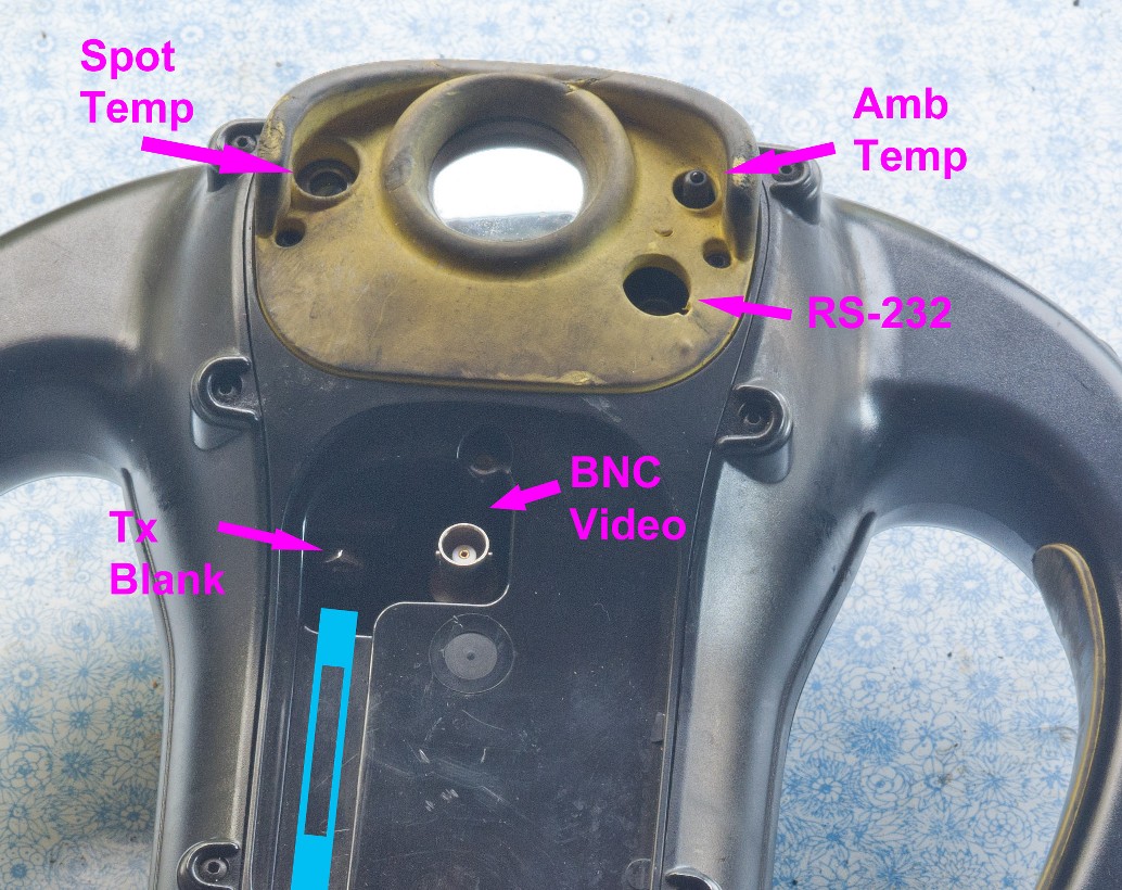
Under the yellow front panel is the video out BNC connector, and also provision for a video transmitter as an at-build option. The video transmitters were analogue RF and country specific. The more common were UK (1394MHz) MPT1349 compliant and US (2454/2472 MHz) FCC part 90 compliant, while there were other frequencies for various countires in Europe.

The top panel area has the RS232 connection, spot and ambient temperature sensors.
The RS232 was sold with a cover, but these are usually lost. Dirt in this conenctor can be a problem and they are VERY expensive to replace. It is a Fischer 102 series 5 pin typically around GBP40 each. A hobby user may prefer to replace with an alternative connector pair especially if they do not have the matching PC cable. The cable pinout details are on this drawing
Note that this is a connection to the camera RS232 port, not the Raytheon core RS232 control.
The ambient sensor is simply a thermistor, so has some lag and cannot magically sense ambient temperature across the room.

The spot temperature sensing, when fitted, is a Raytek module covering 0 - 500°C, necessary because the BST sensor is incapable of performing temperature measurement due to using a ferroelectric detector with a chopper wheel. Dirt or coating degradation will make the reading inaccurate.
The cameras came with user software to allow some control, image download etc and can be found on the CD linked here

Connections

Front panel screws.

Remove to access BNC video or transmitter.
Front panel removed showing BNC.

If fitted, a transmitter antenna sits where the blue box is.
The rear window can be removed for cleaning without opening up the camera.
After removing the rear boot, undo 6 screws arrowed in green
Bottom connections for charging and direct power, also thread tripod mounting.
The direct power bypasses the on/off switch circuits so allows remote use as the camera turns on as soon as power is applied.
Connections on battery PCB. This is of use for testing the camera on a power supply.
0V - battery negative and camera ground
+ve - battery +ve
NC - No connect, to keep the battery sitting straight
Th = NiMH battery thermistor for charge control
3rd - Sensing for primary battery voltage

If using +ve and 0V in place of batteries, the on/off switch is still in the system.

Functional Checks

It is normal to take a substantial period, from typically 30 seconds up to 3 minutes to obtain a stable image from the BST sensor. It takes this long for the sensor to reach the calibrated operating temperature which is then stabilised at 30°C by a peltier heat pump, all controlled by the SECCA.
When checking a camera, much can be assessed by monitoring the current consumption as the camera turns on. The added current draw of the peltier can be seen and there is some protection if there is a fault. 9-12V 3A is necesary for the inrush and initial Peltier surge, a 1A limited supply will simply fold over. The boards DO NOT include reverse polarity or spike protection. Protection should be considered if the camera is not powered from a clean DC supply. A number of 'DIY' conversions to vehicle use have failed as car alternator spikes will kill the BST core, mainly through poorly specified tantalum capacitors. At startup there is a power surge at 10W until the sensor peltier control has stabilised. In normal running, power draw drops to around 3.5W.

Further disassembly

This is covered on the next page here

Batteries and Charging

The Argus 3 used commercial Varta V217 5 x NiMH batteries, 6V 3600mAh, a type for Sony camcorders, and was sold with a commercial charger. An accessory was a charger / storage mount, mainly for truck mounting, and this charged the battery using the camera bottom contacts. It had a power supply in the mount coupled with charge control in the camera. As such input to the bottom contact was a 1A current limited 7.2V supply, the camera only being capable of interrupting this to the battery. The camera charge controller (ICS1702) used pulse/burp charge and also prevented charging if the battery was too hot.
Compatible footprint batteries were also made by Duracell (DR11) and are widely available as clones for Sony camcorders. These batteries normally clipped onto the back of camcorders, so size tolerances were not important. When using with an Argus3 the height and width do matter, so not all batteries will fit.
Some smaller Duracells will need a top padding piece so that the battery dooir closes with the battery meeting the contacts.
Some Chinese clones may need the seam welding trimmed as they can be oversize.


There are two common battery faults. The first is inherent to NiMH in that batteries will seem to charge too soon, but hold no charge, this is common with old or stored batteries. As the battery is charged the internal resistance drops, but to the charger this also looks like the voltage drop of a charged battery, so the charger stops and will show 'charged' when that is plainly impossible. The camera internal charger is less prone to this, or alternatively a manual slow charge direct on the pack (200mA / 24 hour) will restore hte pack to the best it can be.
The second fault is the battery PCB spring contacts breaking. Fire-TICS have spares available for DIY repair

There was also an accessory primary battery pack (ie not supplied as standard with a camera) which is pictured below. This took 8 x AA batteries and so, although intended to take AA alkaline LR6, will take anything that size. For non-fire use the modern LiFeS primaries are an obvious choice, or loose NiMH cells. With either of these types though, the battery gauge will not be accurate as it will be using the discharge profile of the 8xLR6. The contact '3rd' on the PCB (see above) allows the camera to know that a primary pack is fitted, and so to use the 8xLR6 discharge curve, not the 5xNiMH one.

Software Notes

The software is happiest on a WinXP PC, connected direct to a serial port. Users should also note that there is a date bug, so the PC date must be set between 2000 and 2020. Our programmer never thought anyone would be using the software after 2020. This is further discussed here.
However several users have had it working on Win10 with USB-RS232 adapters although I have not doe this myself.

Final Thoughts

The Raytheon BST is still a good quality imager and stands up well against mid and low end bolometers, and the access for reconfiguration is a bonus. The main negatives are that it is bigger and cannot do temperature measurement. There is a fairly steady supply of Argus3 coming to eBay and the likes now, so offering a reasonably cheap way to get quite a good stand-alone imager in a very rugged casing. F-re-TICS has a good spares supply and can also supply tested / repaired cameras (for sale ONLY to UK and EU27 at present) for around GBP400 depending on condition.
For some uses, alternative power sources may be of use, either external or a more modern battery plugged in at the battery PCB.

Back Home
Fire-TICs Argus3 Camera User page 04 July 2023  All tradename © respective owners